
Minimum Pulse Width for a 125 MHz Clock With 45%–55% Duty Cycle
A clock oscillator can meet its frequency and duty-cycle specifications while falling short of the receiver's minimum high or low time. Convert the duty-cycle limits to time and check both pulse widths against the receiver's requirements.
Calculate the period and both pulse widths
Let f be the actual frequency and T = 1/f be the period. If duty cycle D is the fraction of the period spent high at a common measurement threshold, then tH = D/f and tL = (1−D)/f. The lower duty-cycle limit determines the shortest high pulse. The upper limit determines the shortest low pulse. Check both.
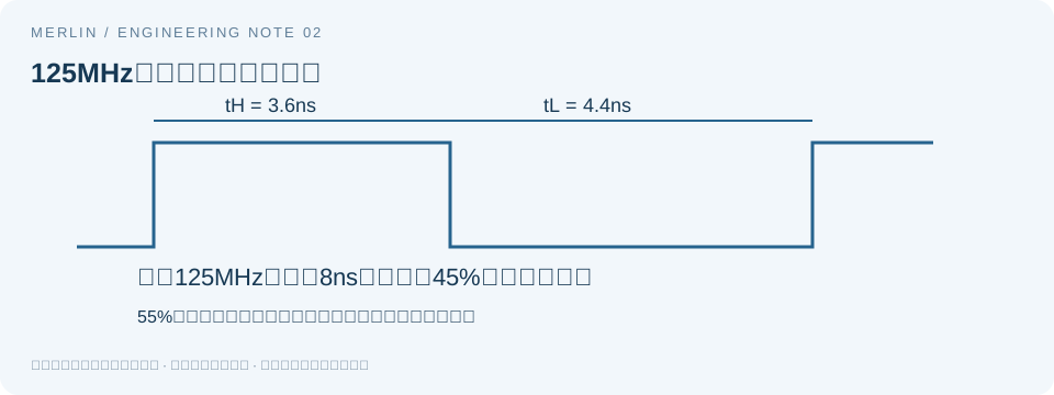
In a hypothetical 125 MHz design, the period is 8 ns and duty cycle ranges from 45% to 55%. At 45%, the high pulse is 3.6 ns and the low pulse is 4.4 ns. At 55%, those values reverse. The minimum for each pulse is 3.6 ns. A typical 50% value yields 4 ns and does not establish that minimum.
| Duty cycle | High pulse width | Low pulse width |
|---|---|---|
| 45% | 3.6ns | 4.4ns |
| 50% | 4.0ns | 4.0ns |
| 55% | 4.4ns | 3.6ns |
Higher frequency further reduces the minimum widths
Suppose the design also allows a positive frequency deviation of 50 ppm. The maximum frequency is 125,000,000 × (1 + 50 × 10⁻⁶) = 125,006,250 Hz. The minimum high pulse is 0.45/125,006,250 seconds, or about 3.599820 ns, and the minimum low pulse is also about 3.599820 ns. Use the maximum permitted frequency because the period shortens as frequency rises.
If the receiver requires at least 3.5 ns for each pulse, the static calculation leaves about 0.099820 ns for each. If it requires at least 3.7 ns, these limits cannot establish compliance. The 50 ppm, 3.5 ns, and 3.7 ns values are hypothetical inputs for the calculation.
Account for the remaining timing margin beyond 3.599820 ns
This calculation covers the frequency and duty-cycle ranges. Treat the result as a per-cycle bound only when the duty-cycle definition, guarantee, and measurement bandwidth cover worst-case behavior on individual cycles. Account for period jitter, pulse-width variation, board-level distortion, and measurement uncertainty according to the system specification.
Subtracting RMS phase jitter from 3.599820 ns does not establish a worst-case pulse width. RMS and peak-to-peak figures have different meanings, and bandwidth and probability matter. Avoid counting the same error twice if it is already included in an overall timing guarantee.
Check the 50% measurement threshold and receiver logic levels
An instrument's duty-cycle reading depends on the selected threshold. A receiver datasheet may define valid high and low time using VIH, VIL, and specified level conditions. When the definitions differ, assess compliance using the receiver's specified intervals. The interval between 50% crossings measures a different quantity.
Rise and fall times can also be specified from 20% to 80%, 10% to 90%, or over another range. Subtracting both edge times from the high pulse width requires a waveform model and a known relationship between the thresholds. Capture the waveform at the receiver pin, save the threshold settings, and check the loading introduced by the probe.
What to record in the acceptance report
Record the full ordering code, guaranteed frequency range, duty-cycle bounds and measurement conditions, both receiver minimum pulse widths and their definitions, both calculated minima, instrument threshold, load, and measurement point. Keep the static calculation and board-level waveform results as separate records.
Manufacturer reference Epson SG2016CBA/SG2520CBA application note, SGxxxxCBA_E_Ver1.0 lists 45/50/55% symmetry in the electrical characteristics table. Section 7-4 shows symmetry under the specified load. The note illustrates how to read the limits under their stated conditions. The hypothetical receiver requirements and frequency deviation above apply only to the worked example.
See also Active Oscillator Pinout, Supply, and Startup Timing. This guide was prepared with AI assistance. The examples use published formulas and hypothetical inputs. Confirm board performance and replacement suitability through testing.