
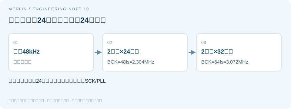
Why 24-bit audio can use a BCK of either 48× or 64× the sample rate
Manufacturer requirements
When specifying audio interface clocks, record the number of valid data bits and the number of clock cycles per frame separately. Multiplying 24 bits by two channels assumes a 24-bit slot, while the configured interface may use a wider slot.
The I²S and left-justified data-format diagrams in the TI PCM512x datasheet show both 48 fs and 64 fs BCK for 24-bit audio. The slot width determines frame timing alongside the data word length. Verify which combinations the selected operating mode supports.
Bit clock calculation and assumptions
For a serial audio frame, use BCK = frame rate × slots per frame × bits per slot. Establish the interface format and slot definition first, since modes carrying 24 valid data bits can use different slot widths.
At a 48 kHz frame rate with two channels and a 24-bit slot per channel, BCK is 48,000 × 2 × 24 = 2.304 MHz. If the same 24-bit data uses 32-bit slots, BCK is 48,000 × 2 × 32 = 3.072 MHz. The word length stays the same while the number of clock cycles per frame changes.
Record BCK, LRCK, and system SCK separately. A BCK combination shown in a data-format diagram still requires verification against the PLL and system clock mode. Review the manufacturer's master and slave mode, system clock, and PLL requirements before specifying the oscillator frequency.
Verification steps
With a logic analyzer, use LRCK to identify a frame, count the BCK cycles in each channel slot, and check data alignment relative to LRCK. For I²S, consult the I²S timing diagram for the first data bit, sampling edge, and bit positions. Left-justified mode has different alignment.
Record the driver configuration, interface mode, valid bits, and slot width. If software changes only the slot width, recalculate and observe BCK before deciding whether the external clock needs to change. When waveform captures are unavailable, record the calculated result and the conditions still to verify.
Verification checklist
| Item or condition | Check or calculated result | Notes and limits |
|---|---|---|
| 48 kHz, two 24-bit slots | 48fs | BCK=2.304MHz |
| 48 kHz, two 32-bit slots | 64fs | BCK=3.072MHz |
| Valid word length | 24 bits | Frame width also depends on slot width |
| Measurement points | Label BCK, LRCK, and SCK separately | Record each clock individually |
Manufacturer documentation and scope
https://www.ti.com/lit/ds/symlink/pcm5122.pdf
MERLIN used AI to help prepare this guide. The manufacturer documentation specifies device requirements, and the worked examples use hypothetical values. Confirm device specifications and compatibility with the applicable datasheet and sample testing.
Related selection guides
For BOM and RFQ preparation, see MERLIN guide to oscillator frequencies and interfaces. Verify the specific part using its manufacturer datasheet and project testing.