
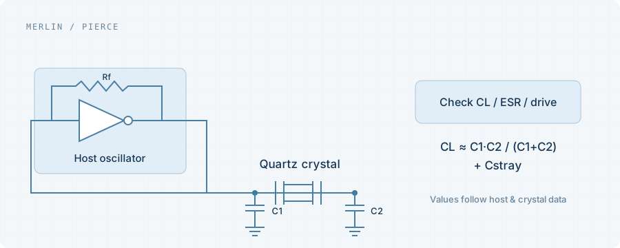
Confirm the circuit and the part
Check crystal versus external-clock mode and identify whether the fitted part is passive or active. Verify ordering code, resonance mode, CL, ESR, pins and orientation before repeatedly changing capacitors.
Review start-up margin and drive
The oscillator needs sufficient gain and negative-resistance margin without exceeding crystal drive limits. Follow the host guide and crystal specification rather than assigning universal resistor or capacitor values.
The probe can change the result
A crystal node is sensitive to added loading. Probe capacitance, grounding and contact position can affect start-up. Record the measurement setup and use a host-buffered clock output where appropriate.
Build a reproducible test matrix
Test cold and warm starts, supply extremes, temperatures and multiple boards. Distinguish consistent failure, intermittent failure and excessive start-up time. Retain waveforms, BOM and board revision for the component review.
Project checklist
- Host and oscillator mode
- Crystal CL, ESR and drive limits
- Supply and temperature matrix
- Probe, waveforms and start-up timing