
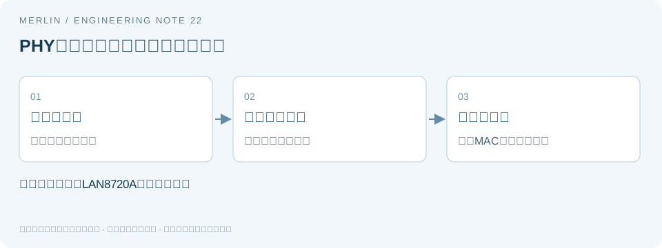
Can the LAN8720A PHY still signal interrupts in reference clock output mode?
Manufacturer requirements
When switching an Ethernet board to use the PHY as the reference clock source, check for the 50 MHz clock and verify what happens to the other function of the shared pin. Include the interface changes that affect the driver in the part substitution records, alongside the clock frequency.
Section 3.7.4.2 of Microchip datasheet DS00002165B states that REFCLKO and nINT share a pin on the LAN8720A and LAN8720Ai. Selecting REF_CLK Out mode disables the interrupt function. Apply this constraint to the specified devices and mode.
Effects on hardware and software
Switching between the 25 MHz and 50 MHz clock arrangements can change which device supplies the reference clock to the PHY–MAC interface, as well as the function of the shared pin. In REF_CLK Out mode, the net previously wired to the host interrupt input carries the reference clock output in place of the nINT signal.
For hardware, review where the clock output goes, its load, and the net connected to the shared pin. For startup configuration, verify the mode selection and when it is latched. For software, identify where the interrupt was used and how the driver will read status after the change. A successful link tests only part of this behavior.
Loss of the interrupt is a requirement the driver change must address. If the system moves to polling, the driver engineer should confirm which status is readable, how it updates, how often to poll, and the power requirements. Verify flag clearing and other register behavior for this PHY specifically.
Verification steps
Begin with a full power cycle and a hardware reset. Confirm the configured mode and actual REF_CLK output, then test link-state handling that previously depended on the interrupt. Record whether the host receives interrupts, how the driver learns about changes, and its response time. Fill in these results during project testing.
Document the PHY clock architecture, external crystal or oscillator specifications, and firmware changes separately. If the change only replaces the clock component and retains the same mode, state that in the change record so reviewers can apply the correct mode-specific constraints.
Verification checklist
| Item or condition | Check or calculated result | Notes and limits |
|---|---|---|
| Pin function | REFCLKO and nINT share a pin | REF_CLK Out mode disables nINT |
| Hardware nets | Clock receiver and existing interrupt net | Check for conflicts and loading |
| Startup configuration | Mode select pins and actual readback | Check power-up and reset |
| Software behavior | Previous interrupt use and new verification items | Verify status handling beyond a successful link-up |
Manufacturer documentation and scope
https://ww1.microchip.com/downloads/en/DeviceDoc/00002165B.pdf
MERLIN used AI to help prepare this guide. The manufacturer documentation specifies device requirements, and the worked examples use hypothetical values. Confirm device specifications and compatibility with the applicable datasheet and sample testing.
Related selection guides
For BOM and RFQ preparation, see MERLIN guide to oscillator interfaces and selection. Verify the specific part using its manufacturer datasheet and project testing.