
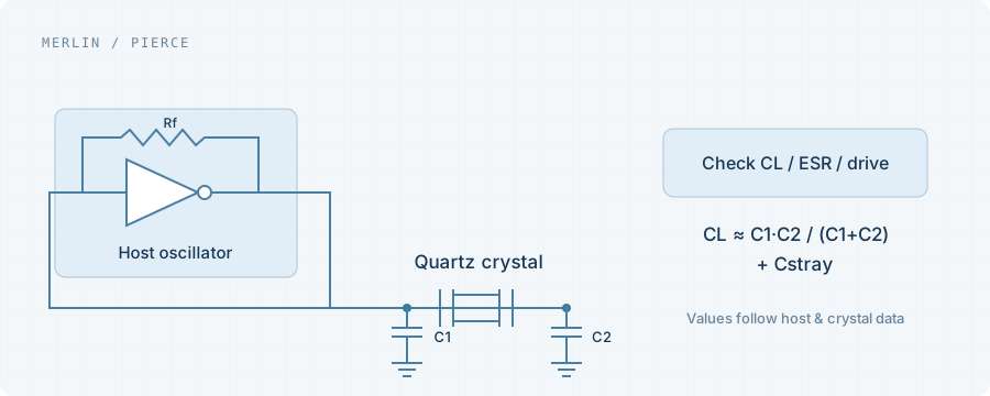
Confirm the specified CL
A parallel-resonant crystal frequency is specified under defined loading conditions. Different circuit loading can shift the operating frequency. Review series-resonant and other designs against their own specifications.
Separate component values from effective load
For a common Pierce circuit, CL ≈ C1 × C2 / (C1 + C2) + Cstray is an initial approximation. Cstray represents effective stray contributions. Use the host reference design and measurements rather than treating this as a universal design rule.
Check start-up and drive as well
Changing capacitors requires more than a frequency check. Verify start-up margin, start-up time and crystal drive. Record device, host and board-test conditions.
What to include in an inquiry
Share the crystal part number, CL, ESR, host IC, external capacitors and temperature range. The existing datasheet is more useful for replacement assessment than frequency and package alone.