
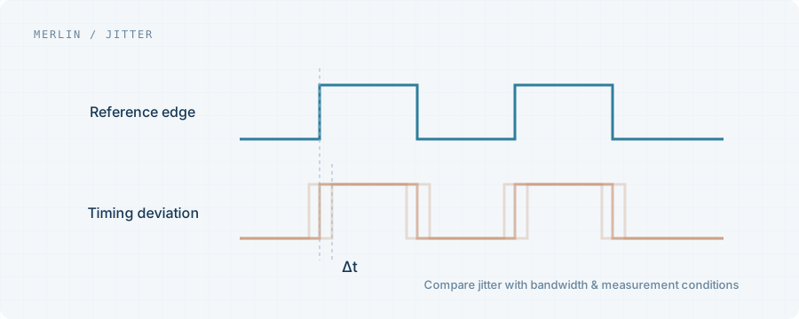
Identify the metric
Period jitter, cycle-to-cycle jitter, integrated phase jitter and a phase-noise curve are different descriptions. Record units, definitions and conditions before ranking values expressed in ps or fs.
Keep the integration band attached
Integrated phase jitter depends on offset-frequency limits. The same carrier can produce different figures with different limits. Compare against the receiving device or system requirement using compatible conditions.
Connections affect the measurement
Termination, load balance and analyzer noise floor can affect a single-ended measurement of a differential source. Keep connection diagrams, power conditions and instrument settings. Laboratory measurements do not automatically describe the assembled system.
Connect the inquiry to validation
Specify carrier, signaling, integration limits, typical or maximum requirement, supply and receiver. Compare samples on a consistent board, load and measurement setup, and record link-level results.
Project checklist
- Carrier and signaling
- RMS definition and integration band
- Typical value or guaranteed maximum
- Instrument, termination and power setup