
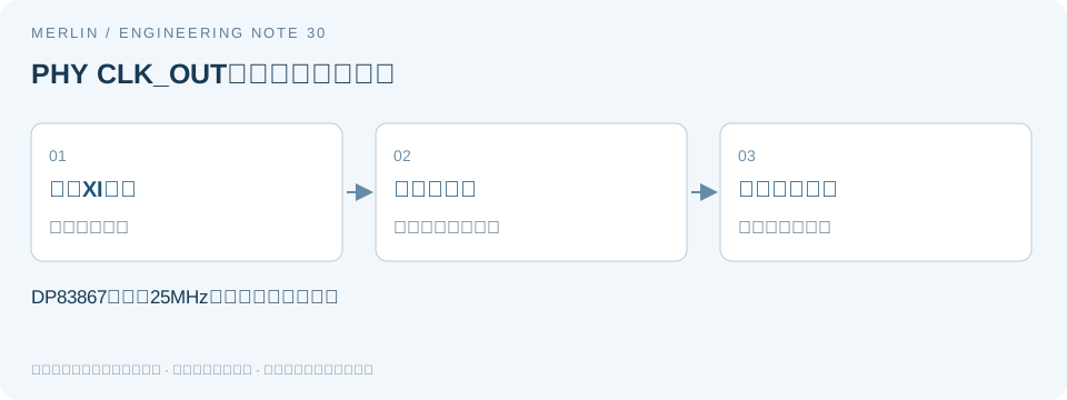
How to distinguish a local reference from a recovered clock at a 25 MHz PHY output
Manufacturer requirements
Two clock modules can measure at the same frequency while using different references. If you measure a PHY clock output, document which internal clock path it selects before attributing the result to the external oscillator.
Section 7.3.3 of the TI DP83867IR/CR datasheet, SNLS484J, describes the internal clock options for CLK_OUT. By default the output is synchronous to the local XI input. Configuration can select a clock synchronous to the received data, whose timing is recovered from data sent by the link partner. A measured 25 MHz output can therefore reflect either clock path.
Interpreting frequency measurements
Record the measurement point, frequency, and reference source as three separate fields. Two 25 MHz clocks have the same nominal period and can have different phase or long-term frequency references. If two measurements use different internal paths, attribution to the external oscillator requires further evidence even when the counter readings are close.
Build a test matrix. First hold the local clock and link partner constant and vary only the selected output source. Then hold the source constant and vary the link state. Changing one factor at a time distinguishes the effect of selecting a different reference from the effect of changing the component. Verify the output state and holdover accuracy after link loss separately.
Suppose the readings are 25,000,000 Hz and 25,000,025 Hz. The difference is 1 ppm relative to 25 MHz. If one reading is from the local path and the other is from the recovered path, the 1 ppm describes the difference between two observations. A component substitution comparison requires measurements on the same path.
Verification steps
First save the configuration and register readback to identify the CLK_OUT selection. Then fix the counter reference, probe load, and measurement point, and record the link state, link partner, and measurement window. Make before-and-after comparisons within each source and keep statistics for the two sources separate.
Confirm software writes with a hardware readback. Save the command, readback, observation time, and waveform in the report. If link-loss behavior matters, run a dedicated test for it. The clock source description leaves holdover capability to be verified.
Verification checklist
| Item or condition | Check or calculated result | Notes and limits |
|---|---|---|
| Output source | Local or recovered, as confirmed by register readback | Group measurements by source |
| Measurement point and reference | CLK_OUT and the counter reference | Compare readings at the same point |
| Link conditions | Link partner, speed, and state | Keep conditions constant for comparison |
| Hypothetical 25 Hz difference | 25Hz/25MHz=1ppm | Verify the cause before attributing it to the oscillator |
Manufacturer documentation and scope
https://www.ti.com/lit/ds/symlink/dp83867ir.pdf
MERLIN used AI to help prepare this guide. The manufacturer documentation specifies device requirements, and the worked examples use hypothetical values. Confirm device specifications and compatibility with the applicable datasheet and sample testing.
Related selection guides
For BOM and RFQ preparation, see MERLIN guide to oscillators and reference clocks. Verify the specific part using its manufacturer datasheet and project testing.