
Start with the signal-chain task
Identify channel selection, intermediate-frequency processing or RF rejection, then state the operating band and signal bandwidth. Compare crystal, LC and other RF structures against the circuit requirement rather than treating their names as a ranking.
State the bandwidth definition
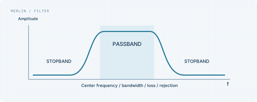
List passband edges, insertion loss, ripple, stopband frequencies and required rejection. Applications sensitive to waveform or phase may also need group-delay limits. Bandwidth figures with different definitions are not directly comparable.
Impedance conditions matter
Published responses use stated source and load conditions. Board impedance, matching networks and parasitics can alter insertion loss and response. Review the test circuit and validate in the intended signal chain.
Prepare a complete requirement sheet
Provide center frequency, passband and stopband mask, impedance, power, temperature, package and existing datasheet. Separate mandatory and negotiable requirements before comparing candidates.
Project checklist
- Passband edges, loss and ripple
- Stopband frequencies and rejection
- Source/load impedance and power
- Package, temperature and test circuit