
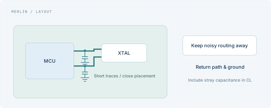
Separate the resonator loop from the output network
A passive crystal loop and an active-clock route serve different functions. The former involves parasitics and the host oscillator; the latter also involves receiver loading, impedance and termination. Apply the appropriate guidance to each.
Start at the supply pin
Review decoupling location, loop length and return continuity. Supply noise can degrade timing behavior. Added filtering also affects voltage drop and transients, so capacitor count alone does not establish an improvement.
Review the route with the receiver
Apply the relevant single-ended or differential signal-integrity rules. Review pair routing, reference planes, branches, vias and termination placement. Component values and coupling depend on the selected driver and receiver.
Validate with representative loading
Recheck frequency, waveforms, jitter and enable behavior with representative power and loads. Record probes and bandwidth, and keep measurement methods consistent across the comparison.
Project checklist
- Decoupling and return path
- Receiver loading and termination
- Clock routes and reference planes
- Waveforms and jitter under matched conditions