
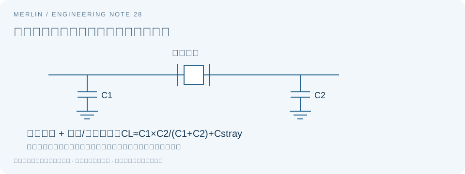
A passive quartz crystal is a resonator that works with an oscillator circuit inside an IC or in external circuitry. A powered oscillator provides a digital clock at its OUT pin. Select a crystal by checking both the crystal specifications and the oscillator circuit.
How a passive crystal works in an oscillator circuit
The crystal's resonance helps set the frequency. An active circuit provides the gain and feedback needed to sustain oscillation. Check the host IC's crystal oscillator mode and external clock input mode separately. Interpret measurements at the crystal terminals as oscillator-node measurements.
Confirm the schematic connections before selecting a device. Passive crystals can use either two-pad or four-pad packages. Some pads in a four-pad device may connect to the case or ground. Use the package drawing to confirm their functions.
Worked example for load capacitance
The simplified two-capacitor Pierce model is CL ≈ C1 × C2/(C1 + C2) + Cstray. If C1 = C2 = 18 pF and the combined effective stray capacitance is 3 pF, CL is about 12 pF. Evaluate this model parameter using the IC input capacitance, layout, and configuration. Avoid counting parasitics twice.
Given a target CL and symmetric capacitor values, the initial estimate for each capacitor is 2 × (CL − Cstray). Verify frequency and startup after selecting initial values. Use the manufacturer's method for programmable internal load, asymmetric capacitors, or a different topology.
Check ESR, negative resistance, and drive together
ESR describes loss in the crystal's equivalent circuit. The oscillator must have sufficient startup margin under the actual load. If you increase the load capacitors to adjust frequency, check startup margin again. Use the specific IC manufacturer's transconductance or negative-resistance criteria.
Drive power depends on crystal current and the effective resistance in the model. With 40 Ω and 0.5 mA RMS, power is about 10 µW. At 1 mA RMS, it is about 40 µW. These hypothetical values illustrate the square-law relationship. Check the datasheet for the allowable drive level.
32.768 kHz crystals and measurement considerations
Real-time clocks commonly use 32.768 kHz, supplied either by a passive crystal or by a powered clock device. For a tuning-fork crystal, verify the IC's supported load, loss, and drive requirements. Use checks specific to that circuit and frequency range.
Connecting a probe to a crystal node adds load and can shift the operating point. Prefer a buffered clock output if the IC provides one, or use the manufacturer's measurement method. Record the probe and grounding arrangement. Test the specified supply, temperature, and power-up conditions, and keep a same-board comparison with the original crystal.
Selection and validation checklist
| Item | What to record | What to verify |
|---|---|---|
| Nominal frequency and load | Series, full part number, CL, and frequency error definition | Compare CL even when frequency matches |
| ESR | Guaranteed maximum and applicable temperature range | Use the guaranteed worst-case value |
| Drive power | Allowed drive and actual crystal current | Use the specified method for crystal current. The digital output voltage alone gives no current measurement. |
| Package and circuit | Land pattern, pinout, case grounding, and IC configuration | Verify device type from the datasheet |
Frequently Asked Questions
Do two 18 pF capacitors give a CL of 18 pF?
In the simplified symmetric model, estimate CL by adding the effective stray capacitance to the series-equivalent capacitance of the two external capacitors.
Can I substitute a part with the same frequency and package size?
Compare CL, maximum ESR, drive conditions, temperature range, frequency tolerance, and land pattern, then validate the complete board.
Manufacturer Reference and Calculation Scope
Epson Crystal Device Glossary for Crystals and Oscillators
This guide draws on public manufacturer documentation and was prepared with AI assistance. The examples use hypothetical values. For design and sourcing, use the full ordering code and matching datasheet, and confirm samples and supply terms separately.